PV COMP is device for transformation of DC voltage generated on the terminals of the solar panel to three phase AC power grid with reactive power compensation capability, specially designed for cooperation with large gensets in hybrid microgrid systems. The current not used for the active power generation from PV panels can be used for reactive power compensation, even during the night or cloudy weather.
PV COMP 350 is transformerless inverter designed for direct connection of a inverter or arbitrary number of parallel ranged inverters on the primary side of the transformer with ratio 0.35/11-33 kV.
Inverters of the PV COMP 350 family are able to operate in wide range of input voltage – voltage of photovoltaic cells within the range from 580 V to 850 V at the rated grid voltage. Design and structure of PV COMP family is made according to specific solar power plant application. Maximum power of the inverter is 150 kVA, it was chosen as an optimal power in consideration of service characteristics: modularity of the solution, maintenance, service, partial shading of PV panels, number of strings and failure of the solar power plant part.
Main features of PV COMP:
Basic technical data
| PV COMP 350 / 100 | PV COMP 350 / 125 | PV COMP 350 / 150 | |
|---|---|---|---|
| Output | |||
| Rated AC apparent power | 100 kVA | 125 kVA | 150 kVA |
| Max Active Power | 100 kW | 125 kW | 150 kW |
| Max Reactive Power | 100 kVAr | 125 kVAr | 150 kVAr |
| Rated output current | 165 A | 207 A | 248 A |
| Input | |||
| Rated input current UDC = 600 V | 154 A | 192 A | 230 A |
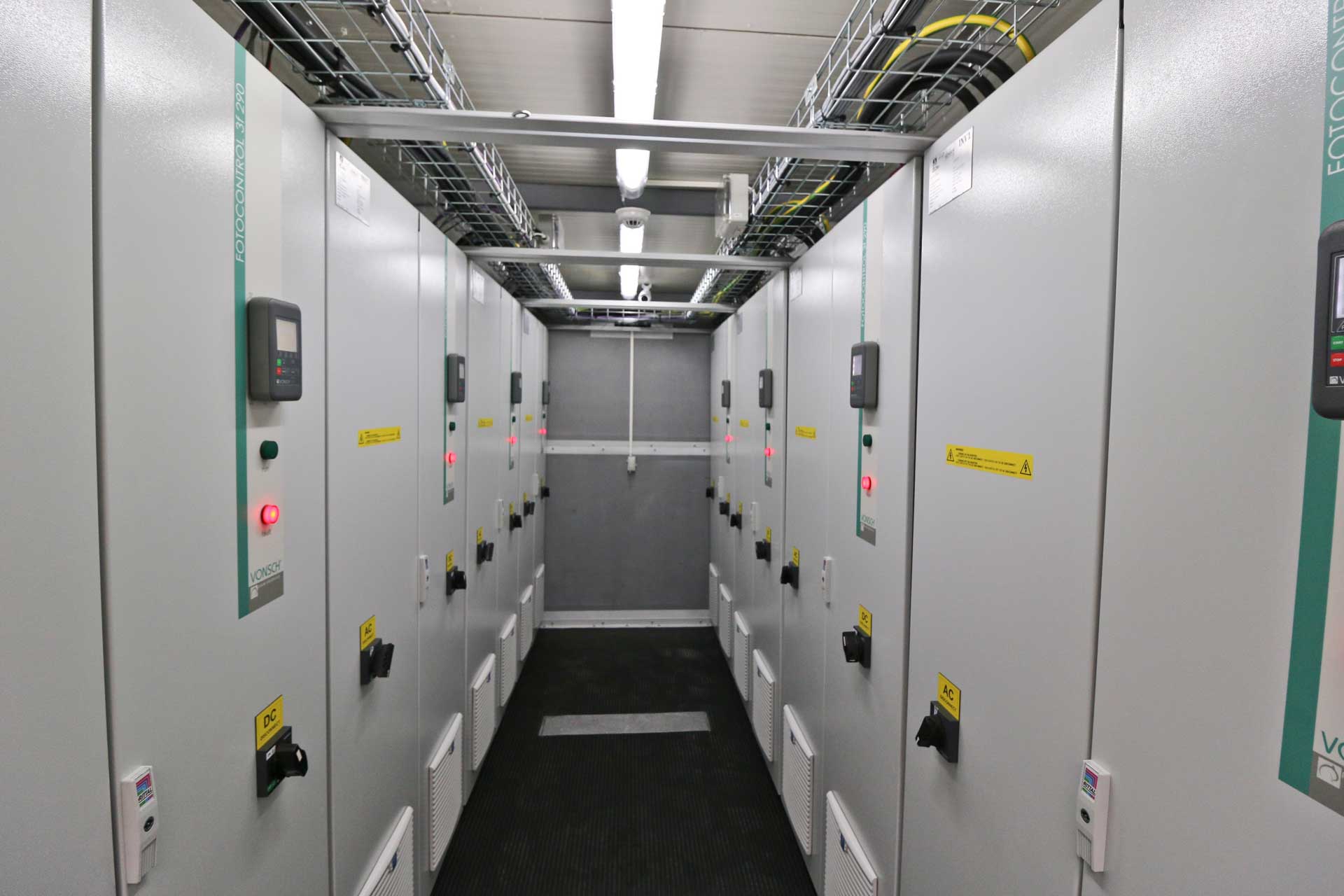
| Dimensions (w x h x d) | 800x1800x500 | 800x1800x500 | 800x1800x500 |
| Weight | 300 kg | 300 kg | 300 kg |
| Peek DC supply voltage | 880 V no load |
|---|---|
| MPPT operating voltage | 580 to 850 V |
| Output voltage | 3x 350 V ±10% |
| Efficiency | ≥ 98 % |
| Euro efficiency | ≥ 96.5 % |
| Output frequency | 50 Hz ± 0.5 Hz |
| cos φ | Adjustable from 0.00 to 1.00, in both inductive and capacitive directions (default=1.0) |
| Total harmonic distortion of the output current (THDi) | Max. 3 % at rated current (THD of the grid ≤ 1,5%) |
| RFI filter | Inbuilt input DC filter and output AC RFI filter |
| Control system | 32 bit. µP DSP - TI |
| Communication | RS 485, USB, CAN |
| Communication module - Optional | Profibus DP, Modbus RTU, Ethernet, GSM |
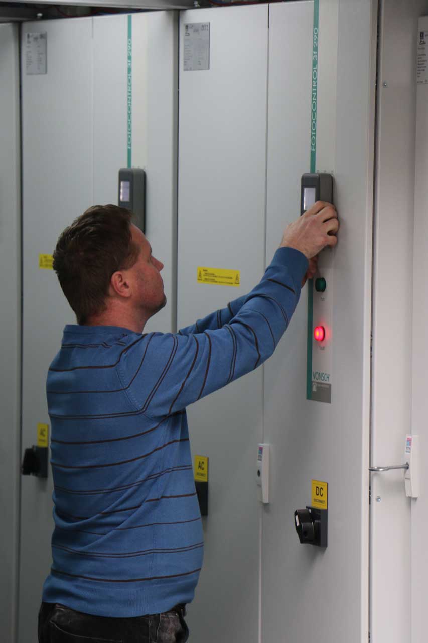
| Contactor at the output | YES |
| Time of disconnection from the grid if the grid is defective | ≤ 10 ms |
| Control panel - Optional | Graphic, detachable, programmable |
| Analog inputs | 4 /0 (4) – 20 mA/ / 0 (2) – 10 V/ |
| Analog outputs | 3 /0 (4) – 20 mA/ / 0 (2) – 10 V/ |
| Relay output | 3 x relay, adjustable, programmable |
| Protections | Current overloading, overvoltage protection of DC inputs and panels , overvoltage protection on the AC side, undervoltage, overvoltage, earth connection on the AC output, cut off between output phases, overheating of the inverter |
| Cooling | Forced air cooling by inbuilt ventilators |
| Absolute altitude of the permitted usage | ≤ 1000 m over the sea, at higher altitude levels reduction of the power for each 100 m of altitude reduction of the inverter power for 1 % |
| Relative humidity of the air | ≤ 95 % without corrosive and explosive gases, without water vapor and condensates |
| Ambient working temperature | + 0 °C to + 40 °C (-20 °C to + 40 °C with optional tempering) |
| Storage ambient temperature | - 25 °C to + 50 °C |
| Protection | IP54 |
| STN EN standards compliance | Safety EN 50 178 EMC emissions STN EN 61000-6-1,3 Harmonic distortion: STN EN 61000 – 3 – 11, STN EN 61000 – 3 – 12 |
| Instructions EEC | 2004/108/EEC, 2006/ 95/EEC |