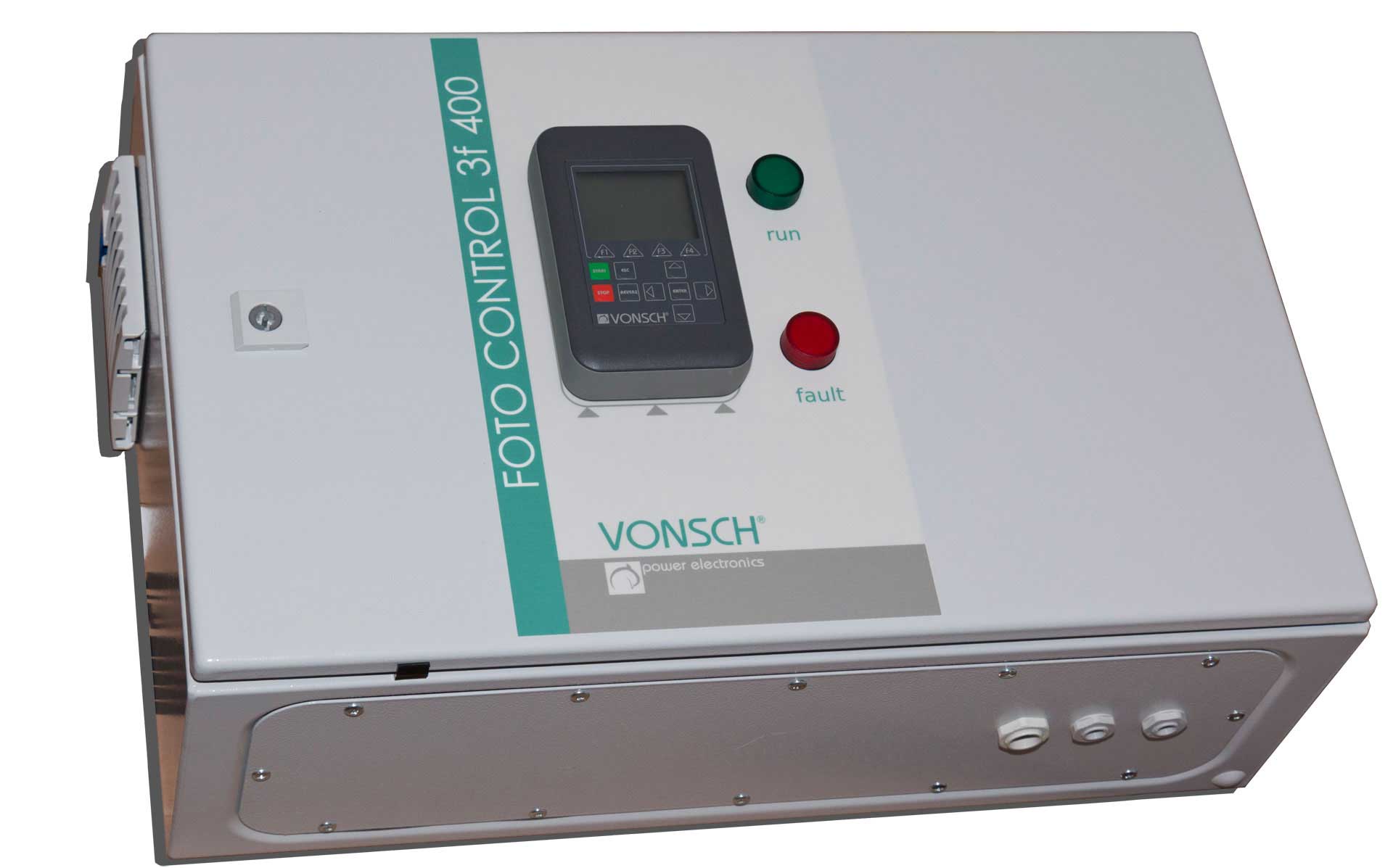
FOTO CONTROL 3f 400 is device for transformation of DC voltage generated on the terminals of the solar panel after impact of photons to three phase AC power grid.
FOTO CONTROL 3f 400 is a transformerless inverter designed for direct connection of a inverter or arbitrary number of parallel ranged inverters on the primary side of the grid transformer with ratio 0.4/22 kV.
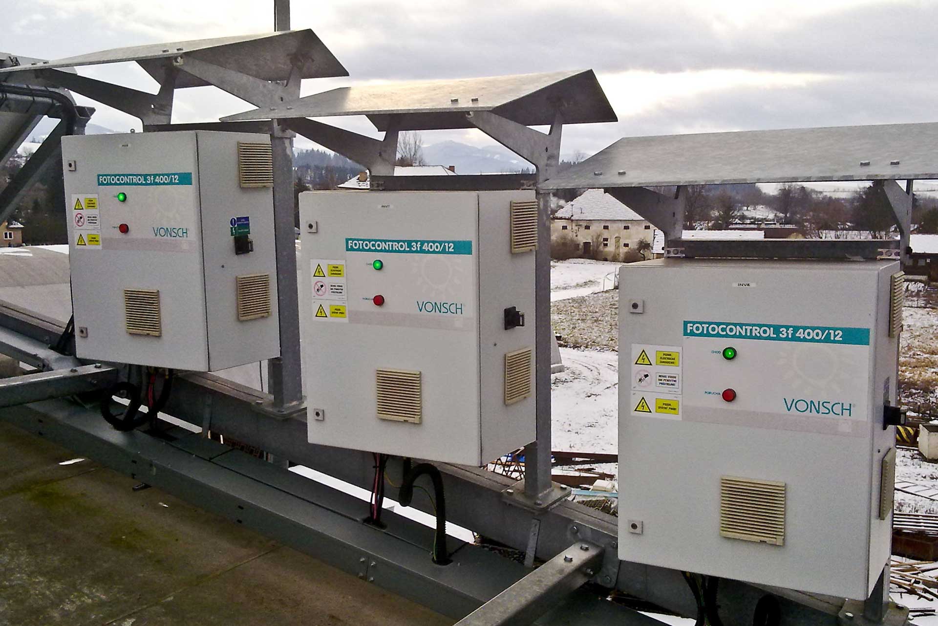
Inverters of the FOTO CONTROL 3f 400 family are able to work in wide range of input voltage – voltage of photovoltaic cells within the range from 450 V to 800 V at the rated grid voltage. The selection and structure of particular types is made according to specific solar power plant application. Three basic versions with power 6, 12.5, 33 and 40 kW are available. The suitable assignment of mentioned types and their number is an ideal solution for solar power plants with the power to 1 MW, it is also easily possible to use them for larger plants. The maximal power of the inverter is 40 kW, it was chosen as a optimal power in consideration of service characteristics: modularity of the solution, maintenance, service, , obscuration of the solar power plant part, number of strings or failure of the solar power plant section.
The main advantages of using FOTO CONTROL 3f 400:
Basic technical data
| FOTO CONTROL 3f 400/10 | FOTO CONTROL 3f 400/20 | FOTO CONTROL 3f 400/33 | FOTO CONTROL 3f 400/100 | FOTO CONTROL 3f 400/125 | ||
|---|---|---|---|---|---|---|
| Output | ||||||
| Rated AC power | 10 kW | 20 kW | 33 kW | 100 kW | 125 kW | |
| Rated output current | 14.3 A | 28.6 A | 47.7 A | 143 A | 179 A | |
| Input | ||||||
| Rated input current UDC = 600 V | 17.5 A | 35 A | 58.3 A | 175 A | 219 A | |
| Dimensions (w x h x d) | 600x800x350 mm | 600x1100x400 mm | 800x1300x500 mm | 1000x2100x500 mm | 1000x2100x500 mm | |
| Weight | 90 kg | 185 kg | 260 kg | 385 kg | 385 kg |
Technical data FOTO CONTROL 3f 400
| Peek DC supply voltage | 850 V no load |
|---|---|
| MPPT operating voltage | 450 to 800 V |
| Output voltage | 3x 400 V ±10% |
| Efficiency | ≥ 98 % |
| Total efficiency | ≥ 96.5 % |
| Euro efficiency | ≥ 95 % |
| Output frequency | 50 Hz ± 0.5 Hz |
| cos φ | Adjustable from -0.9 capacitive to -0.9 inductive (default = -1) |
| Total harmonic distortion of the output current (THDi) | Max. 3 % at rated current (THD of the grid ≤ 1,5%) |
| RFI filter | Inbuilt input DC filter and output AC RFI filter |
| Control system | 32 bit. µP DSP - TI |
| Communication | RS 485, USB, CAN |
| Communication module - Optional | Profibus DP, Modbus RTU, Ethernet, GSM |
| Contactor at the output | YES |
| Time of disconnection from the grid if the grid is defective | ≤ 10 ms |
| Control panel - Optional | Graphic, detachable, programmable |
| Analog inputs | 4 /0 (4) – 20 mA/ / 0 (2) – 10 V/ |
| Analog outputs | 3 /0 (4) – 20 mA/ / 0 (2) – 10 V/ |
| Relay output | 3 x relay, adjustable, programmable |
| Protections | Current overloading, overvoltage protection of DC inputs and panels , overvoltage protection on the AC side, undervoltage, overvoltage, earth connection on the AC output, cut off between output phases, overheating of the inverter |
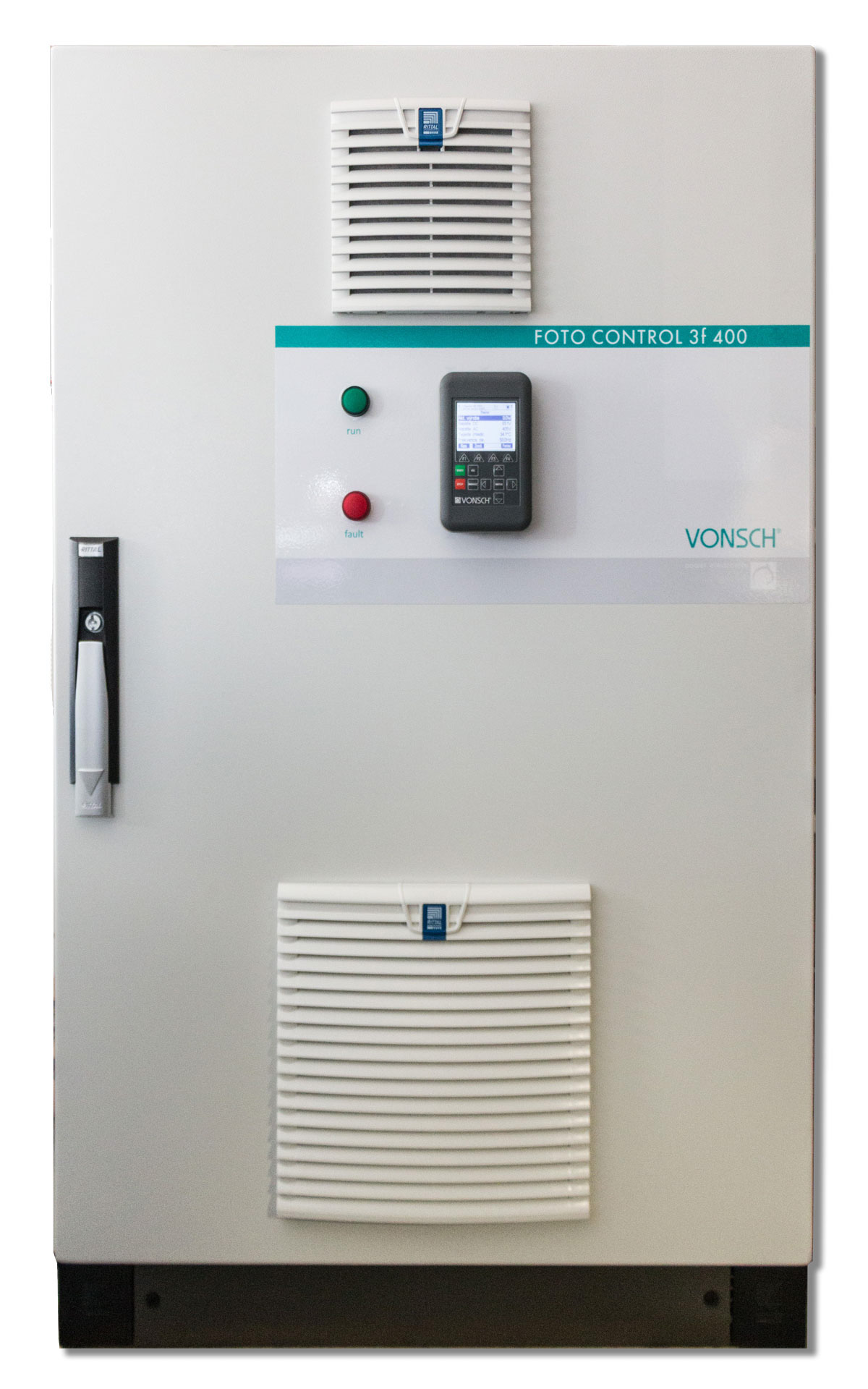
| Cooling | Forced air cooling by inbuilt ventilators |
| Absolute altitude of the permitted usage | ≤ 1000 m over the sea, at higher altitude levels reduction of the power for each 100 m of altitude reduction of the inverter power for 1 % |
| Relative humidity of the air | ≤ 95 % without corrosive and explosive gases, without water vapor and condensates |
| Ambient working temperature | + 0 °C to + 40 °C (-20 °C to + 40 °C with optional tempering) |
| Storage ambient temperature | - 25 °C to + 50 °C |
| Protection | IP54 |
| STN EN standards compliance | Safety EN 50 178 EMC emissions STN EN 61000-6-1,3 Harmonic distortion: STN EN 61000 – 3 – 11, STN EN 61000 – 3 – 12 |
| Instructions EEC | 2004/108/EEC, 2006/ 95/EEC |